Bridge Problem Statement
A century-old bridge that crosses a river valley in a mountainous region must be
replaced. The bridge carries heavy truck traffic to and from mines that are the basis for
the economy of this rural region, as well as providing access and emergency services to
residences. A quick replacement is necessary because no other crossing is available for
miles.
The Tennessee State Department of Transportation (TDOT) has requested design/build
proposals for replacing the existing bridge. Any appropriate type of bridge will be
considered, but TDOT has specified wood as the material because of its availability and
ease of construction. The bridge must carry specified patterns of traffic and wind loads
without exceeding deflection limits. In order to expedite environmental approvals, no
piers may be used in the river.
The stone abutments of the existing bridge are in good condition and will serve for the
new bridge, provided that no lateral thrust or uplift is applied to the abutments. TDOT
will not permit modifications of the existing abutments. The new bridge, when complete,
must be supported only by the existing abutments; for example, stays and anchorage to the
riverbanks are prohibitive.
Your company's design/build proposal is among those that TDOT has deemed responsive.
TDOT has asked each competing firm to submit a 1:20 scale model to demonstrate its
concepts. To facilitate the testing of scaled models, corrugated chipboard will
be used instead of wood.
TDOT will evaluate the models by multiple criteria including efficiency and
economy. The contract will be awarded to the company that submits the best model.
For design purposes, assume standard medium weight chipboard has a modulus of elasticity
of 35,000 psi, cost about $0.05/in.3,
and weighs approximately 0.03 lb./in.3.
Safety
Safety has the highest priority. Judges are directed to disqualify
bridges that cannot be safety constructed or load tested using the abutments and other
equipment provided. Collapse or deflection in excess of limits specified in these rules
will result in disqualification.
Scoring
Categories of competition are
efficiency and economy. The efficiency of a bridge is measured by the sum of the
normalized weight and deflection (SNWD). The SNWD is computed as:
SNWD = Penalized Bridge Weight
(lb.) + 25 lb./in. x Mid-Span Vertical Deflection (in.)
The total cost of the model must not exceed $4.00. If the cost
of the bridge exceeds the upper limit, an additional weight penalty will be imposed as
follows:
Penalized Bridge Weight (lb.) = Bridge Weight (lb.) + (Cost - $4) x
10
lb./$
Bridge Construction Rules
-
Bridges must be constructed using standard medium-weight
chipboard panels. The chipboard can be cut and glued together to developed
any section required by the design team. Chipboard panels should have a
thickness between 0.050 to 0.100 in. Figure 1 shows typical 12 in. x 12 in. x
0.05 in. chipboard panels.

Figure 1. Medium weight chipboard panels.
-
Any type of glue is allowable.
-
Members of the bridge may be built-up for multiple layers of
chipboard to form any thickness and shape required for the design.
Individual chipboard sheets cannot be coated or treated in any way.
Figure 2 shows a method for staggering joints in a compose construction of
chipboards to achieve any various thicknesses. In this case, five sheets are
glued together to develop a 12 in. x 24 in. panel with a thickness of 0.25
in.
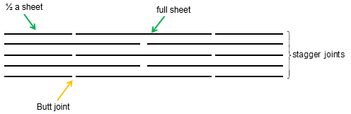
Figure 2.
Composite chipboard construction
-
The bridge must be designed to fit on the support shown in
Figure 3. Members
must span between the tops of the support to simulate a road surface. Members may brace
off only the top surfaces of the support. Members may not brace off the sides or the
horizontal bottom of the support.
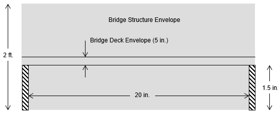
Figure 3. Bridge Supports and Geometrical Constraints
The beam span is 20 in. (remember to allow additional length to account
for the supports). The minimum width of the beam is 2 in. and the maximum
width of the beam is 4 in.
-
The actual bridge will be composed of multiple beams
sections; however, for scale model testing only one beam section is
required. All bridges must support a uniform 300 lb. distributed over
6 in.
at the center of the bridge (see Figure 4). Failure is defined as collapse or deflection resulting in contact between
the bridge and the horizontal base of the support. Deflection will be measured
at mid-span of the bridge (see Figure 5).
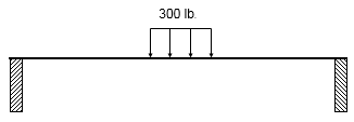
Figure 4. Uniformly Distributed Load
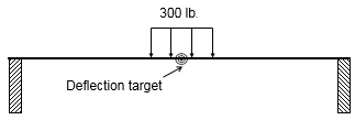
Figure 5. Deflection Targets
-
The traffic deck may be no more higher than 5 in. and must span the entire
length of the bridge.
-
Each team may submit only one bridge.
-
Bridge performance will be measured by a SNWD. The team with the lowest
SNWD will be
awarded the contact.
Bridge Report
-
A written report is required for each wood bridge
submitted for evaluation. The content and quality of the report will account
for 75% of the project score. The remaining 25% of the project grade will be
determined by the strength of the bridge based on the sum of normalized
total weight and deflection (SNWD). There are two strength criteria for
bridges: 1) all bridges must have a SNWD < 10 lb. (20% all-or-nothing -
bridges with a SNWD < 10 lb. receive 20 points; bridges with a
SNWD
> 10 lb. receive no points); and 2) the bridge with the lowest SNWD is awarded full points
(5%) and the remaining bridges will be awarded scores commiserate with their
performance (first place will be awarded 5 points, second place 4 points, third place
3
points, etc.). If a bridge does not
meet the construction rules, listed below, the submitting student will receive no bridge
points.
-
The bridge report should include, but not limited to the following:
I. Title page - name, date and course information
II. Introduction - design and report requirements
III. Bridge Design - a complete set of plans for the bridge
IV. Bridge Analysis - a complete design and analysis of the bridge
including: the location of the point on the bridge where the shear force and
the bending moment are maximum for the applied loads, the variation of
shear force and bending moment for the dead loads, and estimation of the
deflection at mid-span for the load case. Also, include a prediction of the
SNWD for the bridge. Show evidence that you refined and optimized your
structure during the design process.
V. Summary - summarize the strengths and weaknesses of your design and give a
prediction for the SNWD.
-
If
possible, all bridge sketches should be produced using graphical software.
Schedule
Date |
Event |
|
March 19, 2019 |
Rules
and instructions |
|
April 23, 2019 |
Final
report due and bridge testing |
|