 Design Report
-
A written report is required for
each K'NEX structure submitted for evaluation. The content and quality of the report will
account for 50% of the project score. The remaining 50% of the project grade will be
determined by the strength of the structure based on the ultimate strength-to-weight ratio
(SWR). There are two strength criteria for structures: 1) all structures
supporting the design loads (30% all-or-nothing); and 2) the structure with the highest
SWR is awarded full points (20%) and the remaining structures will be awarded scores
commiserate with their performance (first place will be awarded 20 points,
second place 19 points, third place 18 points, etc. . .). If a structure does not meet the construction rules, listed below, the
submitting student will receive no strength points.
-
The design report should include,
but not limited to the following:
-
Title page - name, date and
course information
-
Introduction - design and report
requirements
-
Structural Design - a complete
set of plans for the structure
-
Structure Analysis - a complete
design and analysis of the structure including the force in each member for the applied
load. Assume the modulus of elasticity of the K'NEX plastic is
E = 377 ksi.
Figure 1 show the typical cross-section of a
K'NEX rod. The cross-sectional properties for this section are: I
= 8.8 x 10⁻⁵ in4 and A =
0.031 in2. Also,
include a prediction of the ultimate load of your structure. Show evidence that you
refined and optimized your structure during the design process.
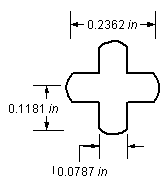
Figure 1. Typical K'NEX Rod Cross-Sectional Area
-
Summary - summarize the strengths
and weaknesses of your design and give a prediction for the ultimate load and SWR.
-
All structural sketches should be produced using
graphical software.
Construction Rules
-
Structures must be constructed
using only K'NEX pieces.
-
Glue is not allowed in
construction of the structure.
-
K'NEX members cannot be coated or
treated in any way.
-
The structure must be designed to fit on the support shown
in Figure 2.
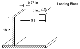 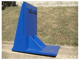
Figure 2. Structure
loading scenario and dimensions
-
The structure must cantilever at least 9 in. from the
support. The height of the structure must not exceed 14 in. The
height of the structure will be determined from the lowest point on the
support to the highest point on the structure. The structure must be a
minimum of 2 in. wide. A tolerance of 1/8 in. will be granted on
all envelope dimensions.
-
The cantilever structure must include a connection to the support. In
other words, your cantilever structure should connect to the vertical
support wall. Figure 3 shows details of the wall connection.
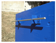 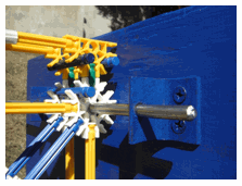 Figure
3. Structure
loading scenario and dimensions
-
All structures will be loaded via a 3 in. by 3 in.
loading block (see Figure 2) to the design load of 60 lb. or
to the point of failure which occurs first. Failure is defined as the point
when the structure can no longer support an increased load or collapse.
-
Each student may submit only one structure.
-
Structural performance will be
measured by a strength-to-weight ratio (SWR) computed in the following manner:

where P is the ultimate
load (lb.) and Wstructure is the
weight of
the structure (lb.).
-
The cost of each structure will
be estimated using the following
cost sheet. A
Cost
Factor will be computed as follows:

where Maximum Bridge Cost is the maximum bridge cost in the
competition and Your Bridge Cost is the cost of each competitor's
structure.
-
An adjusted SWR computed as SWRAdjusted
follows:

-
The structure with the highest SWRAdjusted will win the event.
-
Any modifications or repairs to
the structure must be done before registration. Once the structure is registered, no other
changes may be made.
Schedule
|
Date |
Event |
|
February
6, 2020 |
Rules and
instructions |
|
February 21, 2020 |
Prototype Testing (out of class) |
|
February 25, 2020 |
Final report and
testing |
|


