|
For the
72-bar truss shown below, determine the displacements and elemental stresses.
Nodes 1, 2, 3, and 4 are pin connections. Let E = 107
psi
and the A = 1.0 in2 for the first two stories and A =
0.5 in2 for the top two stories. Table 3 lists the values and
directions of the two loads cases applied to the 72-bar space truss.
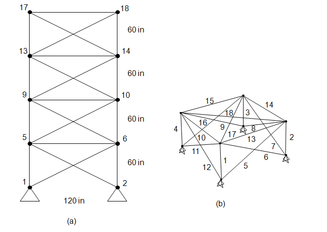
Table 3. Multiple Loading Conditions for
the 72-Bar Truss
|
Case |
Node |
Fx
(kip) |
Fy
(kip) |
Fz
(kip) |
|
1
|
17 |
0.0 |
0.0 |
-5.0 |
|
18 |
0.0 |
0.0 |
-5.0 |
|
19 |
0.0 |
0.0 |
-5.0 |
|
20 |
0.0 |
0.0 |
-5.0 |
|
2 |
17 |
5.0 |
5.0 |
-5.0 |
|
|
This web site was originally
developed by
Charles Camp for
CIVL
7117.
This site is
Maintained by the
Department of Civil Engineering
at the University of Memphis.
Your comments and questions are welcomed.
|