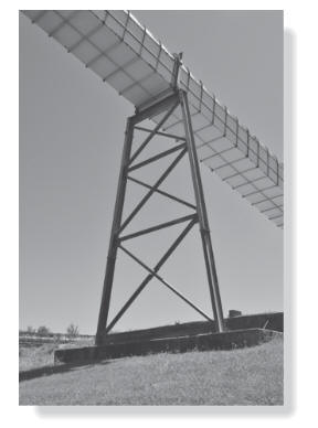
The steel-trussed bent shown in Figure 1(a)
supports a portion of the pedestrian bridge.
It is constructed using wide-flange sections
for the columns and the top beam, which
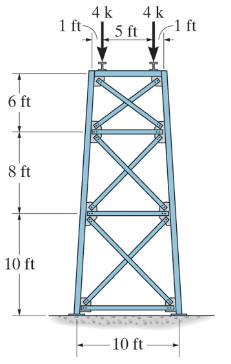
supports the bridge loading, estimated to be
8 k, as shown in Figure 1(b).
The ends of the top beam are welded to the
columns, and the bottoms of the columns are
welded to base plates, which are, in turn,
bolted into the concrete. The internal truss
elements are bolted at their ends to gusset
plates, which are welded to the web of each
column.
Use the SAP2000 model you developed for
17-3P and design the appropriate elements
using the Steel Frame Design tool.
Hand in a copy of the
coverpage
and an image displaying the selected
sizes and stress ratios from the Steel Frame
Design tool.
(a)
(b)
Figure 1. Structural bent support a
walkway (a) photograph, and (b) geometry and
loading.
Table 1 lists the
wide-flange sections that should be considered
for the columns and the top beam.
Table 1. Available Wide
Flange Steel Beams (“W” Shape)
Table 2 lists the round
tube sections that should be considered for this
design.