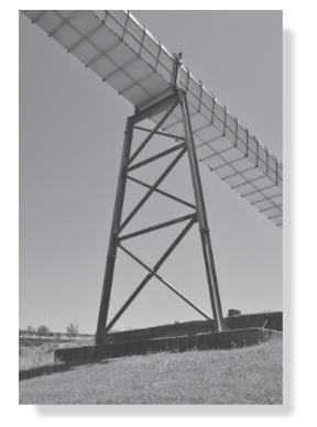
The steel-trussed bent shown in the photo is
used to support a portion of the pedestrian
bridge. It is constructed using two
wide-flange columns, each having a
cross-sectional area of 4.44 in
2 and a
moment of inertia of 48.0 in
4. A similar
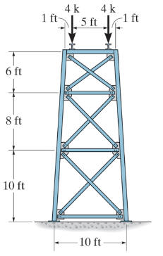
member is used at the top to support the
bridge loading, estimated to be 8k as shown in
the figure. The ends of this member are
welded to the columns, and the bottoms of
the columns are welded to base plates which
in turn are bolted into the concrete.
Each
truss member has a cross-sectional area of
2.63 in
2,
and is bolted at its ends to gusset plates.
These plates are welded to the web of each
column. Establish a structural model of the
bent and justify any assumptions you have
made. Using this model, determine the forces
in the truss members and find the axial
force in the columns using a computer
program for the structural analysis. Neglect
the weight of the members and use the
centerline dimensions shown in the figure.
Compare your results with those obtained
using the method of joints to calculate the
force in some of the members. Take
E =
29(10
3) ksi..
Hand in a copy of the
coverpage
and an image displaying the selected
sizes and stress ratios from the Steel Frame
Design tool.
(a)
(b)
Figure 1. Structural bent support a
walkway (a) photograph, and (b) geometry and
loading.