The following is a step-by-step procedure for analyzing a two-dimensional truss
structure using SAP2000 (v20). The order of some of these steps is not critical; however,
all steps should be completed before starting the analysis. If you have questions
or find the instructions unclear or inaccurate, please contact
Dr. Charles Camp.
The following tutorial will focus on determining the forces in each
roof truss member shown below to help students become familiar with some of the
numerous aspects and features of SAP2000. Assume all
members are pin-connected.
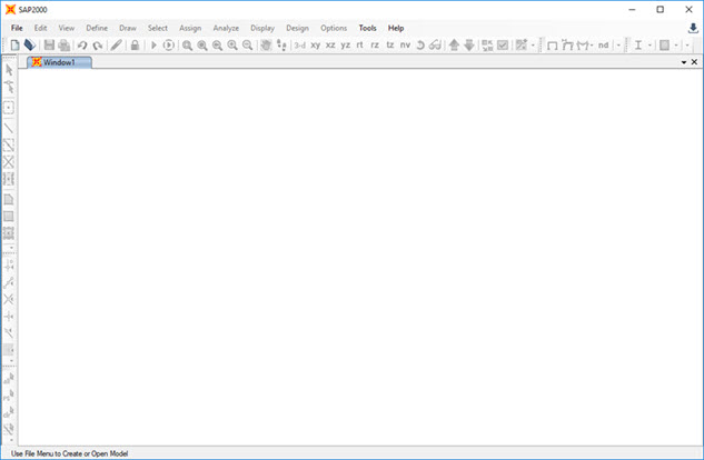
When you start SAP2000 Version 20, you should see the
following interface window:
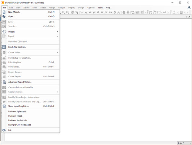
Step 1: New Model - To
start a new problem, select New Model
under the File menu.
The New Model
window gives many different templates
for general structures. In this example, we will
use the Grid Only template.
To use the grid, determine the appropriate number of
grid lines and spacing to locate the truss joints.
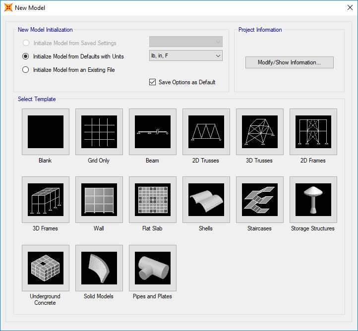
On this menu, you can
select the units for the problem; the default is
lb, in, F. You can change the unit when
necessary and, SAP2000 will convert the values. In this example, the default units are
acceptable.
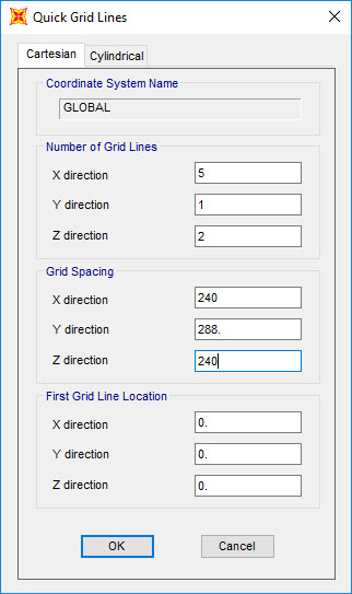
| When
you select Grid Only on the menu, the Quick Grid Lines
window will appear (see the figure on the right).
SAP2000 assumes that your two-dimensional structure resides in the x-z plane.
Define
your grid system by entering data on the Quick Grid Lines
window. For the truss shown above, the grid spacing in the x and z-directions is 240
in. The number of grid lines in the x and z-directions are 5 and 2,
respectively. Only one
y-direction grid line is necessary for 2D problems.
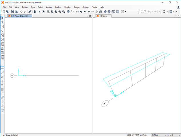
When you click OK, SAP2000 generates the grid lines you have just
defined and shows you the grid system in the SAP2000 interface window.
By default, SAP2000 displays two views of your problem, typically a 3-D and x-y
plane view. To adjust the views, select a window and click the appropriate view button
at interface window's the top edge. |
|
 |
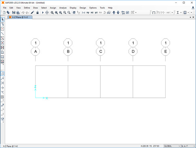
Click on the window label and delete the
left-hand side window so that you have a general
3D view, and then click on the xz
button on the top bar to see a 2D view of the
structure.
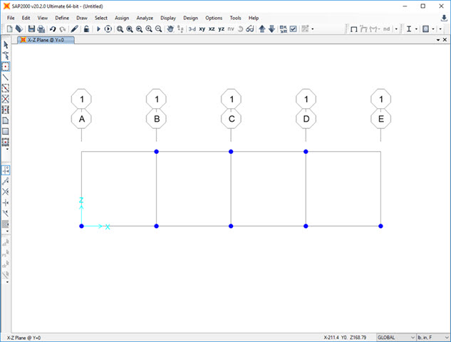
Step 2: Locate Truss Joints - Select the Draw Special Joint button  on the
left side toolbar to define the joint locations. Click on grid intersection lines to define joints. For this problem, the
joint locations are shown below:
on the
left side toolbar to define the joint locations. Click on grid intersection lines to define joints. For this problem, the
joint locations are shown below:
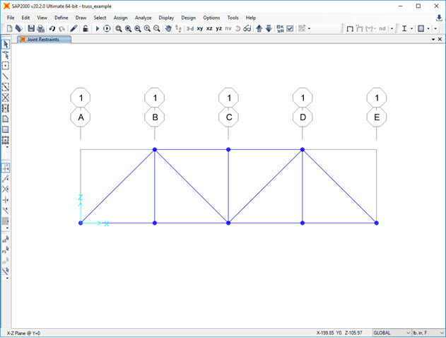
Step 3: Draw Frame Elements - Select the Draw Frame Element button
 on
the left toolbar to define each frame element. The Properties of Object window will appear.
We can select a frame object you want to draw or use the default
and update the frame element properties later.
on
the left toolbar to define each frame element. The Properties of Object window will appear.
We can select a frame object you want to draw or use the default
and update the frame element properties later.
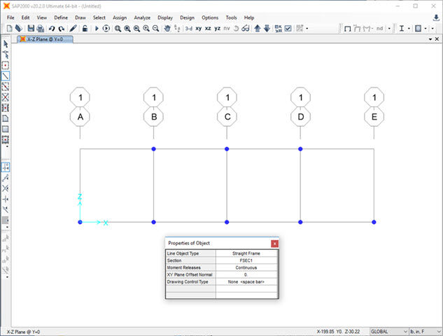
In this example, we will just
use the default properties. Close the
Properties of Object window and begin
to draw frame objects. To define an element, click on a joint at the beginning of the element
and then on the joint at the end of the element. To end a series of element definitions,
double-click on the final joint. For this truss problem, the frame elements are
shown below:
Step 4: Define Structural Supports -
To define the location and type of structural support, select the support
location by clicking on the joint with the pointer. A blue "X" should appear at
the joint to indicate it is currently selected. Next, click on the Assign
tab at the top of the SAP2000 interface, then click on Joint, and then
the Restraints
... button on
the bottom toolbar.
|
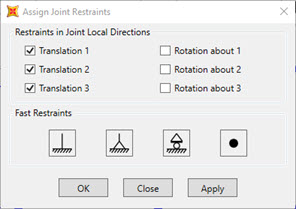
The Assign Joint
Restraints menu will appear as shown on the right. Usually, the directions 1,
2, and 3 listed on the menu correspond to the x, y, and
z directions. The Fast Restraints
button may be used for most problems when working on two-dimensional
strucutres. If the support conditions for your problem are not
listed in the Fast Restraints section of the menu, you should select the
appropriate combination of restraints.
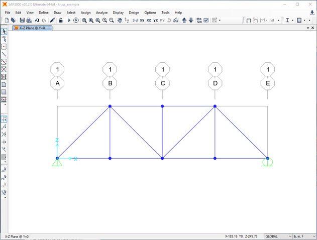
In the truss example, select the lower-left hand
joint with the pointer (an "X" should appear at the joint), then click on the pin
button  and click OK.
Next, select the lower right-hand
joint with the pointer and Fast Restraints menu, select the roller
button
 and click OK. and click OK. |
 |
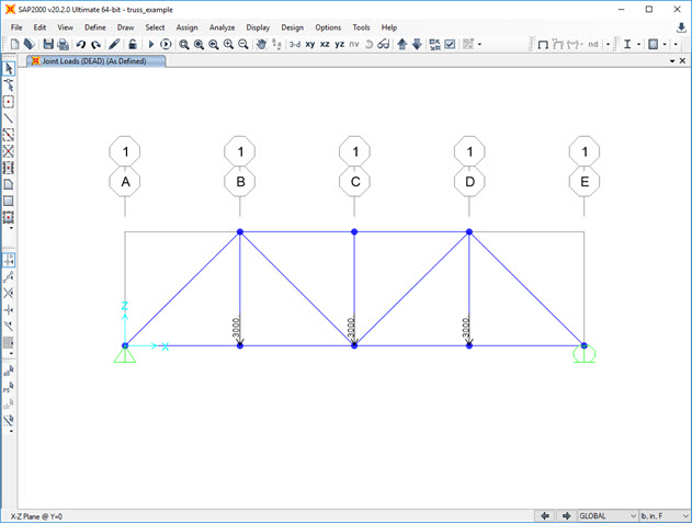
After the supports have been defined, the truss problem should appear in the SAP2000
interface window as follows:
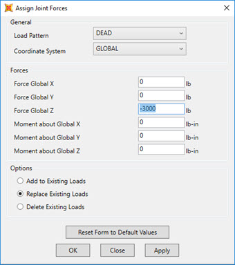
Step 5: Apply Forces at Joints -
To apply forces at a joint, select the joint with the pointer and click on
Assign,
then Joint Loads, and then Forces. The following menu will appear:
|
In this
example, three 3,000 lb. forces acting along the bottom chord of the truss. Remember
that the truss was modeled in the x-z plane; therefore, the forces act in the
negative z-direction. Enter -3000 in the Forces Global Z input field and
click OK.
The forces should be displayed on the truss (proper
direction and magnitude) in the SAP2000 interface window. |
 |
Step 6: Set Analysis Options -
This example models the truss structure in the x-z plane in this example. To limit analysis to
variables in the x-z plane, click on the Analyze menu at the
top of the SAP2000 interface window and then click on Set Analysis Options. The Analysis
Options menu will appear as follows:
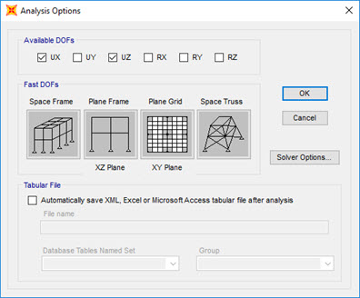
To restrict SAP2000 to variables in the x-z plane, select
the Plane Frame button,
uncheck the RY box, and
click OK. The truss structure is now ready for analysis.
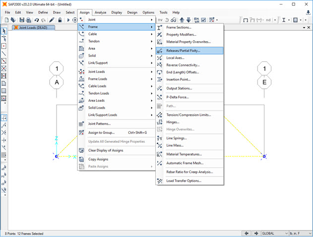
Step 7: Release Internal Moments at Joints - SAP2000
assumes all structures are frames. Therefore, we should
convert each joint from a fixed to a pin-connection to define each frame element.
To ensure every joint
in the structure is pin-connected, select all the members by clicking the Select
All button on the left-side toolbar. Next, click on the Assign menu,
select Frame, then Releases/Partial
Fixity..., and then and an
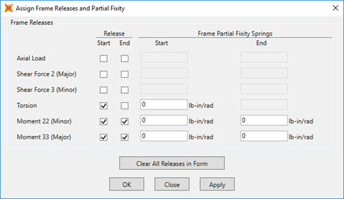
Assign Frame
Releases and Partial Fixity window will appear.
|
In this
example, the structure is a truss with no moment capacity at each joint.
Click on the checkboxes associated with Moment
22, Moment 33, and Torsion to
release the moment capacity. Torsion can only be
released at one end of the element, whereas the other moment must be released at both the
Start and End of the element.
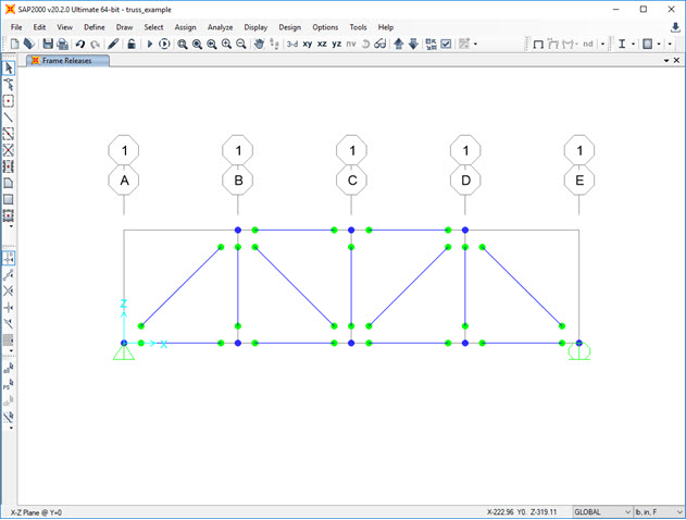
After the moments are released, the truss structure should appear in the SAP2000
interface window as follows: |
|
 |
Step 8: Define Material Properties - SAP2000 assumes the
loads acting on a structure, including the weight of each element. In our truss analysis, we
assume that each element is weightless. To define the properties of a material, select
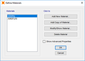
the Define menu at the top the SAP2000 interface window and
then click on Materials. The Define Materials window will appear as shown
below:
 |
|
On this menu,
you can change the properties of materials. Select the
A992Fy50 (steel with a yield stress of 50 ksi)
material in this example and click the Modify/Show Material... button.
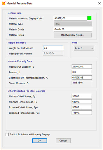
The Material Property Data window will appear.
|
Change the
value in the Weight per unit Volume input field to zero. Click OK to return to the Define Materials window, then click OK again. Now, we have a material named
A992Fy50 that has no weight per volume.
For this example problem, the default values for the Mass per unit Volume,
Modulus of elasticity, Poisson's ratio, and the Coefficient of Thermal Expansion can
be used. For most linear elastic statically loaded structures, only values for
Weight per unit Volume and Modulus of Elasticity are required.
Step 9: Define Frame Sections - To define the cross-section
properties of a structural element, click on the Define menu located
at
the top of the SAP2000 interface window, then click on Section Properties,
then Frame Sections..., and then the Frame Properties window will appear as shown below:
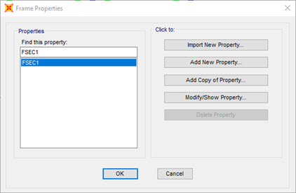
The default
Frame Section label is FSEC1. To change the properties of the frame
section, click on the Modify/Show Property... button.
The I/Wide Flange Section window will appear.
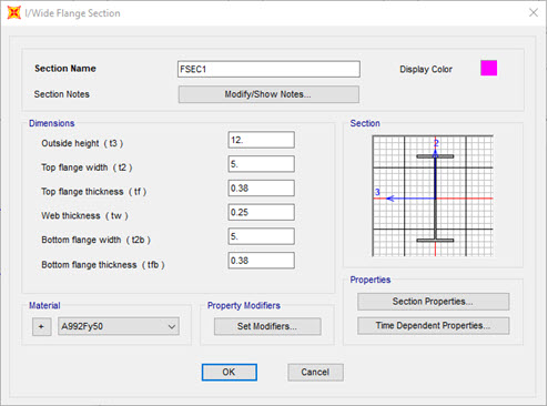
To define the material
of this frame section, click on the Material pull-down menu and select our
weightless material
A992Fy50. Click OK to return to the
Frame Properties
window, then click OK again. If you are interested in
computing deflections in the truss, you must define the cross-sectional
dimensions of each frame element. In this example, we are interested only in the
axial forces in a determinate truss, so the values of the cross-sectional areas
are not required.
Step 10: Assign Frame Sections - To assign the
frame properties of a structural element, select the element with the pointer and
click on the Assign menu at the top of the SAP2000 interface
window, then click on Frame, and then Frame Sections... You can assign the same section
properties to multiple elements by selecting all the elements that share the same properties.
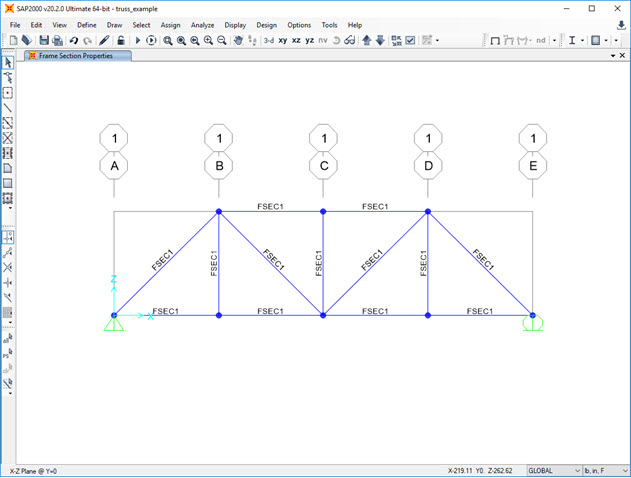
Choose the frame element from the Assign Frame Sections window. The
frame section name will appear next to each element selected. After the frame sections
have been assigned, the SAP2000 interface window will appear as follows:
Step 11: Run Analysis -
To analyze the model, press the Run
Analysis button
 . The Set Load Cases to Run
menu will appear as shown below:
. The Set Load Cases to Run
menu will appear as shown below:
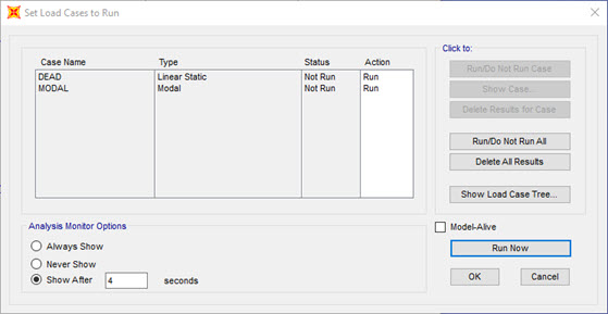
By default, there are two
load cases: DEAD and
MODAL. More load cases can be added,
but only the DEAD
load case is required in this example. Click on
the
Run Now button. If the analysis is successful, the Analysis Complete window will
appear and report that the analysis is complete. Click OK, and the
Save Model File As window will
appear as shown below:
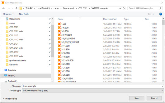
SAP2000 creates about 40 temporary files when
you run a model, so choosing a special folder to
store the SAP2000 files is beneficial. The
Windows Desktop is not a good location. When a
folder is selected, name the SAP2000 model file.
In this example, the file name is truss_example.
SAP2000 will save the model information in the
file named truss_example.sdb in the folder
selected.
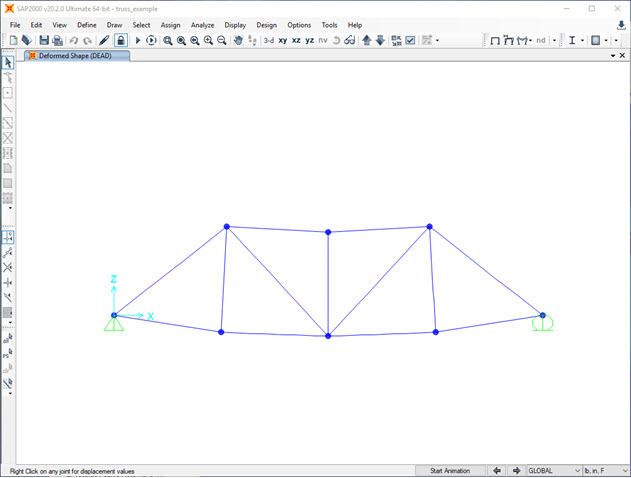
The SAP2000 interface window will display an exaggerated deflected shape of the modeled
structure.
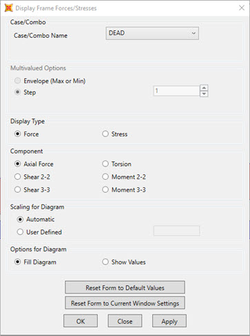
Step 12: Print Truss Forces - To get a quick feel for the
relative magnitude of the forces in the truss, click on the Show
Forces/Stresses pull-down menu
 at the top of the SAP2000 interface, select
Frames/Cables/Tendons..., and the Display Frame
Forces/Stresses menu will appear as follows:
at the top of the SAP2000 interface, select
Frames/Cables/Tendons..., and the Display Frame
Forces/Stresses menu will appear as follows:
 |
|
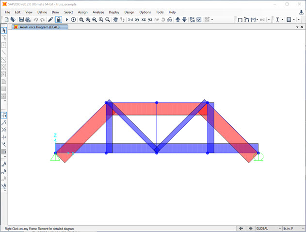
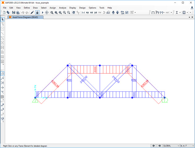
The default
values will display the Axial Forces using the Fill Diagram. If
you click OK, the SAP2000 interface window will display the relative magnitude of the
axial forces with compress forces in red and tension forces
in blue.
Another way to display force information is to unclick Fill Diagram
and click on Show Values on Diagram. In this case, the value of each
axial force will be displayed next to the member (see the figure below). |
To print the results, to a file click on the File menu, select Print
Tables..., and the following menu will appear:
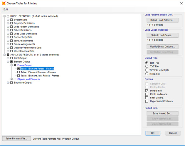
In this example, all we require are the axial
forces in the truss, so click on expand the
Element Output item under the
ANALYSIS RESULTS section, expand the Frame Output item,
and then click on Tables: Element Forces
- Frames. Also, click on the box
Print to File and the
TXT file button to define the file format.
Click OK and define the name
and location of the TXT file.
There is an option for
Spreadsheet Format if desired. The default location for the file is the same
directory as the problem files. A different location can be specified by
clicking File Name and choosing the desired file location and name.
Turn on the frame labels turned to correlate the results printed in the
output file to frame elements in the structure. Click the Show Undeformed Shape button
 on the
main interface to display the frame element labels. Next, click on the Display Options button
on the
main interface to display the frame element labels. Next, click on the Display Options button
 and under
the Frame section of the menu, click on Labels.
and under
the Frame section of the menu, click on Labels.
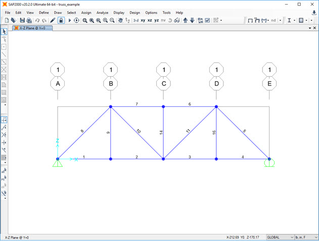
The frame element numbers or any other information displayed in the main
SAP2000 interface can be printed by clicking on the File menu and
selecting Print Graphics (the image will be sent to the default printer).
The results of the truss analysis presented in the output file are listed by
frame element number.
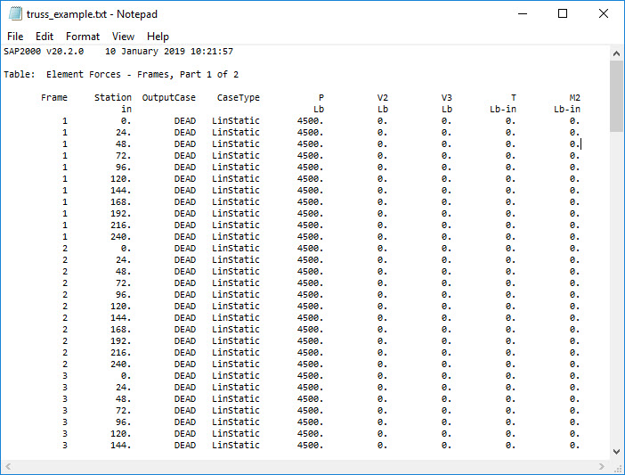
Note that SAP2000 lists the variation of the internal forces and moments along
the element. For truss analysis, there are no bending moments and shear forces.
The values listed in the "P" column are the axial forces in the truss members.