|
The following is a
step-by-step procedure for analyzing a
two-dimensional frame using SAP2000 (v24). The order of some of these steps is not
critical; however, all steps should be completed
before the execution of the analysis. If you
have questions or find instructions unclear or
inaccurate, please get in touch with
Dr. Camp.
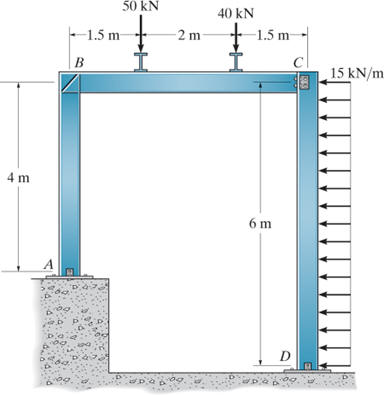
Draw the shear and moment diagrams for each of
the three members of the frame. Assume the frame
is fixed and connected at A, B,
and D, and with a pin joint at
C. Assume E is 200 GPa, A = 20 (103) mm2,
and I is 300 (106) mm4.
Click here for a
cover page for this problem
When you start SAP2000
Version 24, you should see the following
interface window:
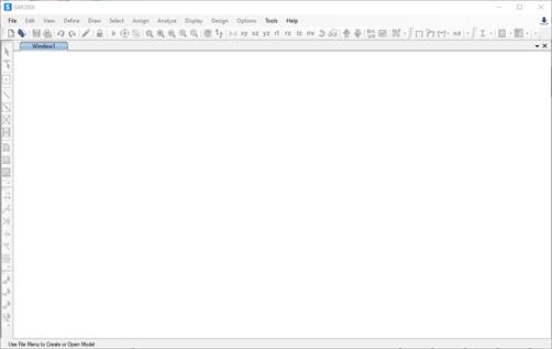
Step 1: New Model - To start a new problem,
select New Model under the File menu.
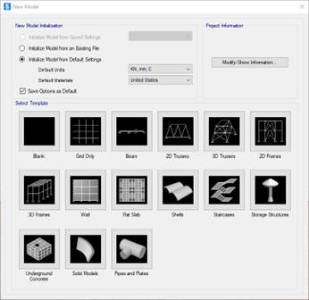
The New Model window
gives many different templates for general
structures. On this menu, you can select the
units for the problem; the default is kN, m,
C. You can change the unit when
necessary, and SAP2000 converts the values. In
this example, the units are kN and
m.
Click on the 2D Frame icon on the first row
of templates.
The
Frame template
menu should appear.
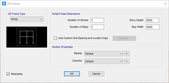
In this example, the frame has one bay of 5,000
mm (5 m) and a one-story height of 6,000 mm (6
m). Enter the values and click OK.
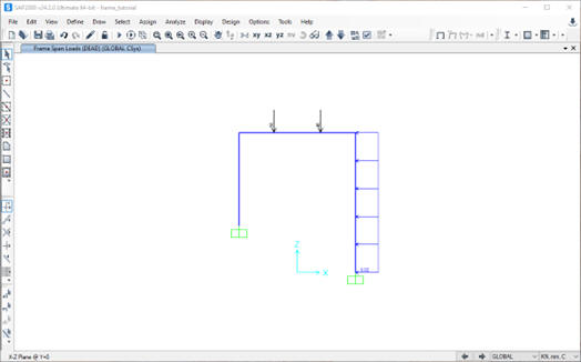
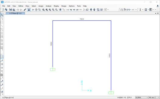
The SAP2000 interface displays the geometry of
the frame. By default, the supports are pins.
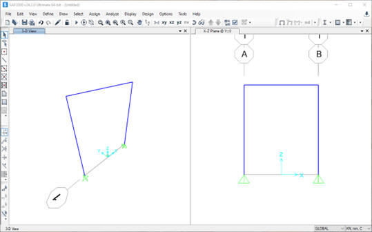
Since we do not need a 3-D
view of the beam, click on the window label and
delete the left-hand side window so that you
have an xz view of the beam.
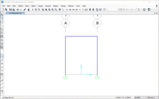
This example’s grid lines are unimportant, so
they are turned off. Click on the View
menu at the top of the SAP2000 interface and
then Show Grid.
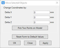
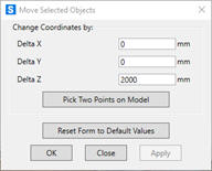
Next, adjust the height of the left column.
Select the bottom node of the element by
clicking on the joint with the pointer. A blue “X”
should appear at the joint to indicate it is
currently selected. Select the Edit
menu at the top of the SAP200 interface, then
Move, and the following menu
appears. In this example, the node moves in the
positive z-direction 2,000 mm (2 m).

Step 2: Define Structural Supports - To define the location and type of structural support,
select the support location by clicking on the
joint with the pointer. A blue "X" should appear at the joint to indicate it is currently selected. Next,
click on the Assign tab at the top of the
SAP2000 interface, then click on Joint,
and then the Restraints ... button on the
bottom toolbar.
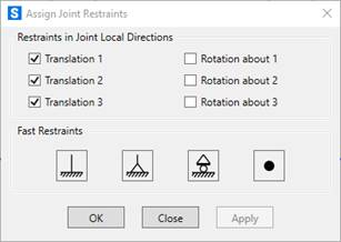
The Assign Joint Restraints menu appears
as shown. Usually, the directions 1, 2,
and 3 listed on the menu correspond to
the x, y, and z directions. The Fast Restraints
buttons may be used for most problems when
working on two-dimensional structures. If the
support conditions for your problem are not
listed in the Fast Restraints section of
the menu, you should select the appropriate
combination of restraints.
In this frame example, the support at
A and D are fixed.
Select the far left node with the
pointer (an "X" should appear at the joint), then click the Fixed button
 and
then OK.
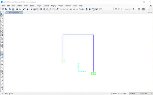
After the supports have been defined,
the beam should appear in the SAP2000
interface window as follows: and
then OK.
After the supports have been defined,
the beam should appear in the SAP2000
interface window as follows:
To model the pin connection at node C,
select the frame element and click on Assign,
Frame, and Releases/Partial Fixity.
The following menu appears.
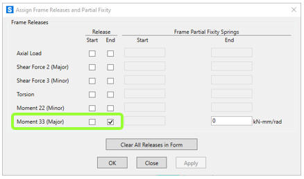
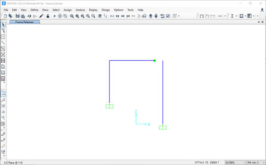
Check the box for Release
End Moment 33 (Major). The moment at the
end of this element are zero. SAP2000 indicates
that a release has been specified with a green
dot and shows a break on the line.
Step 3: Apply
Forces
– Two loads are applied to the
frame in this example.
The top frame element has
two equally spaced point loads, and the
right-side column has a distributed load.
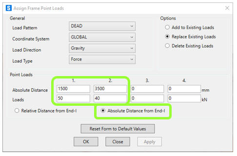
To apply the point loads,
select the frame element with the pointer, click
on Assign, then Frame Loads,
and then Point. The following menu
appears. Click on Absolute Distance from
End-I and enter the position and value of
the two point loads. This example shows a 50 kN
load at 1,500 mm (1.5 m) and a 40 kN load at
3,500 mm (3.5 m) from the left edge.
Click OK, and the loads are displayed on
the frame:
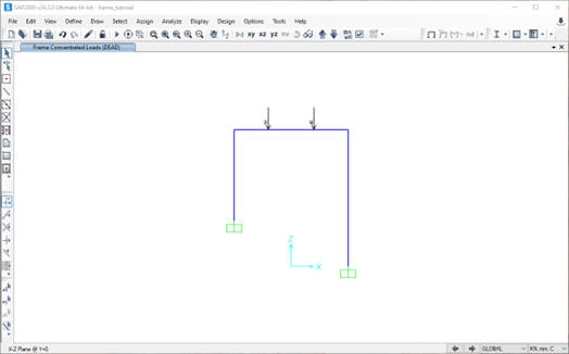
The first beam element has
two equally spaced point loads, and the last
element has a distributed load.
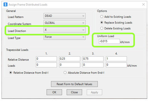
Next, click on the far right element and select
Assign, Frame
Loads, and Distributed.
The following menu should be displayed. In this
example, the distributed load is in the negative
local x-direction and has a value of 0.015 kN/mm
(15 kN/m). Enter these values into the menu and
click OK.
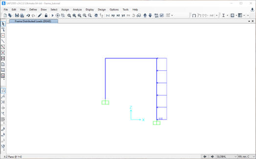
The distributed loading is displayed on the
frame.
<
The point loads are not deleted; they are
currently not displayed. Select Display,
Show Object Load Assigns, Frame,
and then OK to see all frame loads.
Step 4: Set Analysis Options -This example models the
frame in the x-z plane. Click on the Analyze menu
at the top of the SAP2000 interface window and
then click Set Analysis Options to limit
analysis to variables in the x-z plane. The Analysis
Options menu appears as follows:
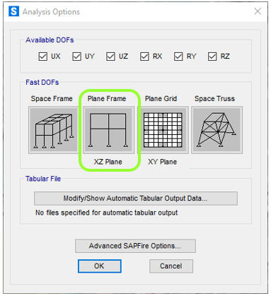
To restrict SAP2000 to
variables in the x-z plane, select the Plane
Frame button and click OK.
Step 5: Define Material Properties - SAP2000 assumes the loads acting on a structure, including the weight of
each element. In our beam analysis, we assume
that each element is weightless. To define the
properties of a material, select the Define menu
at the top of the SAP2000 interface window and
then click on Materials. The Define
Materials window appears as shown below:
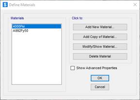
On this menu, you can
change the properties of materials. Select
the A992Fy50 (steel with a yield stress of 50 ksi) material in this example and click the Modify/Show
Material... button.
Material Property Data window
is displayed.
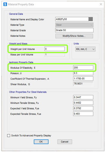
Change the Weight per unit Volume value
to zero and adjust the Modulus of Elasticity,
E, to 200 kN/mm2 (200 GPa). Click
OK to
return to the Define Materials window, then
click OK again. Now, we have a material named
A992Fy50 that has no weight per volume. For this
example problem, the default values for the Mass
per unit Volume, Modulus of elasticity,
Poisson’s ratio, and the Coefficient of Thermal
Expansion can be used. For most linear elastic
statically loaded structures, only values for
Weight per unit Volume and Modulus of Elasticity
are required.
Step 6: Define Frame Sections - To define the cross-section properties of a structural element, click on
the Define menu located at the top of the
SAP2000 interface window, then click on Section
Properties, then Frame Sections..., and
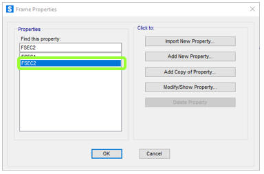
then the Frame Properties window is
displayed.
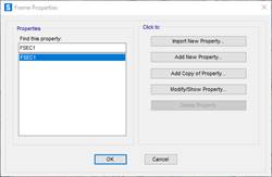
The default Frame Section
label is FSEC1. To change the properties
of the frame section, click on the Modify/Show
Property... button. The I/Wide Flange
Section window is displayed.
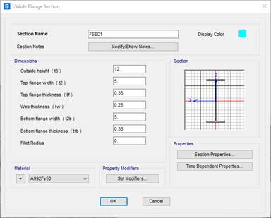
To define the material of
this frame section, click on the Material pull-down
menu and select our weightless material A992Fy50.
Click OK to return to the Frame
Properties window, then click OK again.
In this example, the frame elements have a
cross-sectional area of A = 20 (103) mm2 and a
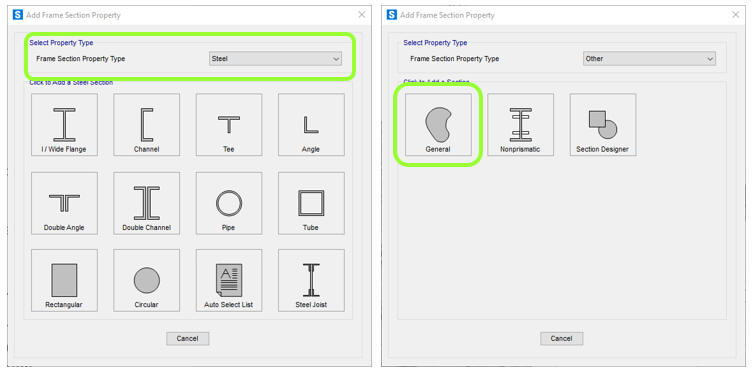
moment of inertia value I = 300 (106) mm4. Click
Add New Property on the Frame Properties menu to
specify this value. The Add New Property menu is
displayed. For this example, click the Frame
Section Property Type dropdown menu, select
Other, and then click on General.
In this example, the
frame
has a moment of inertia value of 1,000 in4.
Click Add New Property on the Frame Properties
menu to specify this value. The Add New
Property menu is displayed. For this example,
click the Frame Section Property Type
dropdown menu, select Other, and then
click on General.
In this example, the frame elements have a
cross-sectional area of A = 20 (103) mm2 and a
moment of inertia value I = 300 (106) mm4. Click
Add New Property on the Frame Properties menu to
specify this value. The Add New Property menu is
displayed. For this example, click the Frame
Section Property Type dropdown menu, select
Other, and then click on General.
The Property Data menu is
displayed. In this example, the Moment
of inertia about the 3 axis (the strong
axis) is 300 (106) mm4. The value of the
Cross-sectional area is 20 (103) mm2
.
The Moment of inertia about the 2
should be a small value of 1 to minimize their
effect on the results.
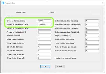
Enter the value and click
OK. Then click OK on the
General Shapes menu, and the Frames
Properties menu is displayed. Note that FSEC2
has been added to the list of sections. Click
OK.
Step 7: Assign Frame Sections - To assign the frame properties of a structural element, select all beam
elements with the pointer and click on the Assign menu
at the top of the SAP2000 interface window, then
click Frame, and then Frame Sections. You
can assign the same section properties to
multiple elements by selecting all the elements
that share the same properties. Choose the
FSEC2 frame element from the Assign Frame
Sections window and click OK.
The frame section name is
displayed next to each element selected. After
the frame sections have been assigned, the
SAP2000 interface window is displayed.
Step 8: Run
Analysis - To analyze the model,
press the Run Analysis button
 .
The Set Load Cases to Run menu is displayed. .
The Set Load Cases to Run menu is displayed.
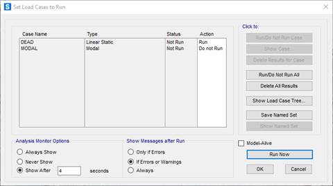
By default, there are two
load cases: DEAD and MODAL. More
load cases can be added, but only the DEAD load
case is required for this example. Click on the
Run Now button. If the analysis is
successful, the Analysis Complete window
is displayed and reports that the analysis is
complete. Click OK, and the Save Model
File As window is displayed.
<
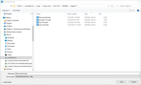
When you run a model,
SAP2000 creates about 40 temporary files, so
choosing a particular folder to store the
SAP2000 files is beneficial. The Windows Desktop
is not a good location. When a folder is
selected, name the SAP2000 model file.
In this example, the file
name is frame_tutorial. SAP2000 saves the model
information in the file named frame_tutorial.sdb in the folder selected.
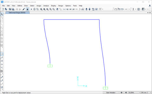
The SAP2000 interface window displays an
exaggerated deflected shape of the modeled
structure.
Step 9: Print
Beam Forces - To get a quick feel for the relative magnitude of the forces in the
beam, click on the Show Forces/Stresses pull-down
menu
 at
the top of the SAP2000 interface, select Frames/Cables/Tendons...,
and the Display Frame Forces/Stresses menu
is displayed. at
the top of the SAP2000 interface, select Frames/Cables/Tendons...,
and the Display Frame Forces/Stresses menu
is displayed.
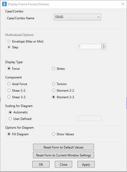
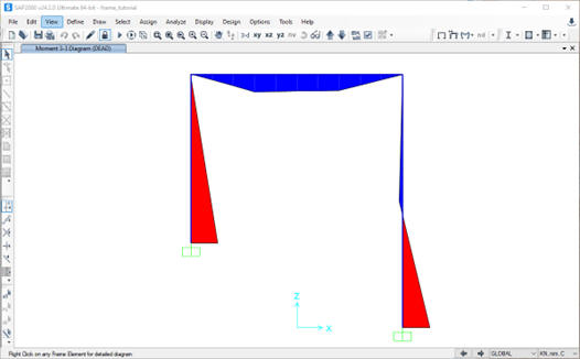
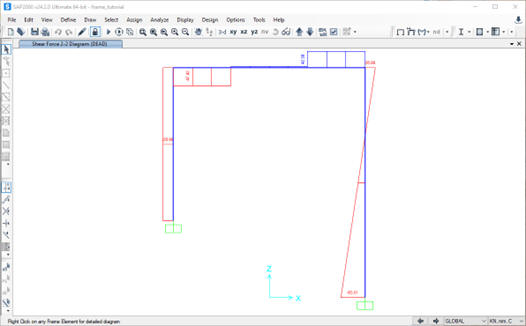
Select the Moment 3-3
(the strong axis) and then OK; the moment
along the frame is displayed.
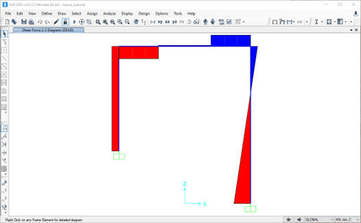
For the shear force, Select the Shear-22 and
then OK; the shear force along the frame is
displayed.
The default view is the Fill
Diagram, where the relative magnitude
of the moments are displayed. Negative bending
moments are in
red and the positive in
blue.
Another way to display
force information is to unclick Fill Diagram and
click on Show Values on Diagram. In this
case, the value of each axial force is displayed
next to the elements.
To view more detail about
the forces along an element, click on the
element in the SAP2000 interface and
right-click. The Diagram for Frame Object
# (FSEC2) window is displayed. Below are the
results for each of the three elements in this
example.
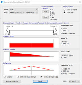
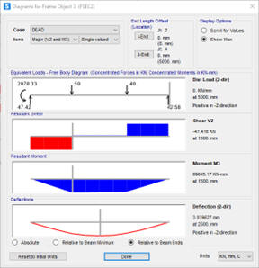
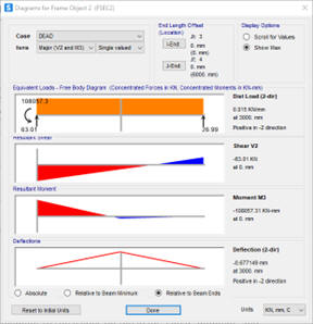
Drag the vertical slider
along the element to see values on the loads,
shear, moment, and deflection.
To print the results to a
file, click on the File menu, select Print
Tables..., and the following menu is
displayed.
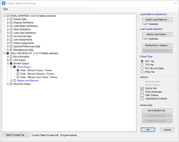
In this example, we
want the shear forces and bending moments in the
frame, so click on expand
the Element Output item under the ANALYSIS
RESULTS section, expand the Frame Output item,
and then click on Tables: Element Forces -
Frames. Also, click on the box Print to
File and the TXT file button to
define the file format. Click OK and
define the name and location of the TXT file.
There is an option for Spreadsheet
Format if desired. The default location for
the file is the same directory as the problem
files. A different location can be specified by
clicking File Name and choosing the
desired file location and name.
Turn on the frame labels to
correlate the results printed in the output file
to frame elements in the structure. Click
the Show Undeformed Shape button / on the main
interface to display the frame element labels.
Next, click on the Display Options button
 and
under the Frame section of the menu,
click on Labels. and
under the Frame section of the menu,
click on Labels.
The frame element numbers
or any other information displayed in the main
SAP2000 interface can be printed by clicking on
the File menu and selecting Print
Graphics (the image is sent to the default
printer).
The results of the
frame
analysis presented in the output file are listed
by frame element number.
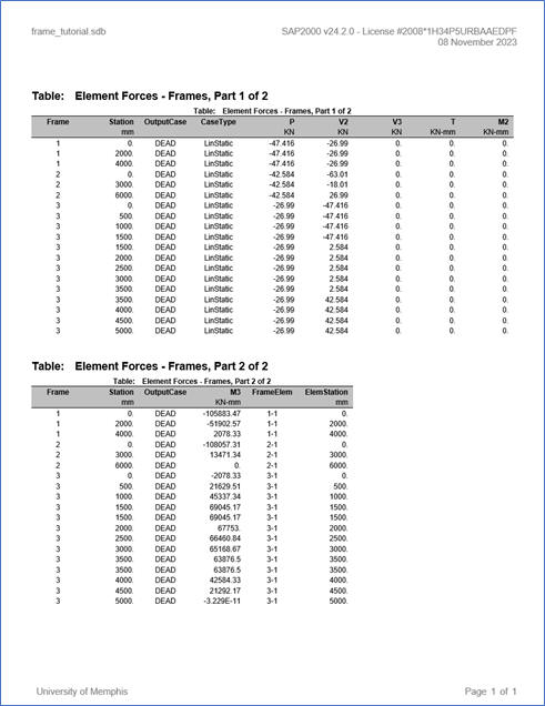
Note that SAP2000 lists the variation of the
internal forces and moments along the element.
For frame analysis, there are bending moments
and shear forces. The values in the “M3” are the
bending moments, and “V2” are the shear forces.
|